11 Aug 2012
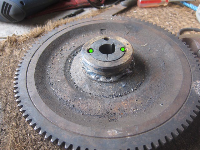
Welded the hub adaptor onto the flywheel. I lined it up by eye, using the
six bolt-holes that were just visible inside as a guide, and spot-welded
inside to get it to stick. Then went round the outside: there was a lip
with a 2mm gap all the way round. Once I'd done that, I realised that
I'd made a serious mistake spot-welding the inside, because, damnit,
that's where the tapered bush fits! So I then had to spend an hour
with a drill (breaking 1 and re-grinding 3, continuously) because of
course the grinder won't fit getting out three blobs of metal. In the
end I actually ground off the last remaining bit off the taperered bush.
Then when it came to fixing the taper-lock bush into the adaptor (holes
marked in green) I couldn't find the hex-bolts! It's all go, here...
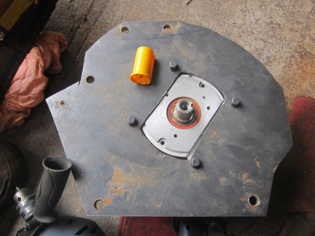
Showing the adaptor plate attached to the motor, finally. Found some 3/8-16
bolts (yay!). Actually cutting out the adaptor plate was a bit of a sod.
Whilst the outside was fine, the inside was hell to do with only an
angle-grinder. But that was nothing compared to drilling the holes. I
started with a 3.3mm, snapped that. Then used the 3.0mm, made 2 guide holes
and snapped that. Then got the 3.5mm and managed to complete the remaining
holes without snapping it. Then started with the 6.0mm, widening the holes.
It took eight minutes per hole (there's 9 of them). I sat there with
a squirty garden water bottle, over the top of the drill, with ear-defenders
on, pushing down on top of the drill and watching the pretty patterns of
water and bits of metal jump up and down on the plate as it screeched and
resonated the entire plate. Oh - then I had to do the 12mm holes, which
took another six to eight minutes each. That was when the fun started.
Holes 1 and 2 were fine, but hole 3 is when the drill jammed, yanked out of
my hand (it was on "lock" so was still running), wrapped the cord around
itself a couple of times, pulled the metal plate off the toolbox, smashing it
against my leg, tripped the fuse on the extension cord and also managed to
pull the plug out of the socket as well. Oh, and snapped the 12mm drill-bit.
So, after that, I was a bit more careful. I re-ground the drill-bit with
the angle-grinder, then got rid of the burrs on the underside hole: they were
actually protruding out a good 8mm, not in a spiral as you'd imagine,
but as a complete unit! It was as if I'd managed to push the hole to project
out of the plate. So the next few holes i left 1mm or so and then ground off
the burrs and then drilled from the opposite side for a bit.
The motor bolt-holes were also a bit of fun, because I'd bought an 8mm drill-bit
when I actually needed a 3/8in drill-bit (8.8mm). So, that had to involve
rotating the drill to cut off the top and bottom edges, then move it sideways
in the hole, using the very last section of the drill bit closest to the chuck
to get the last bits out. All a bit messy but it worked.
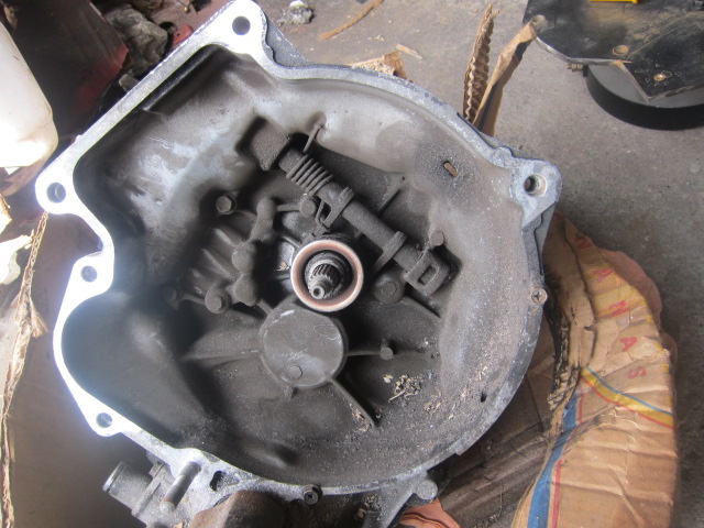
Just a reminder photo of where this is all going. I should have
the holes in the right place, but there is a little bit of play in those
12mm holes in order to adjust things. The absolute most important thing
is that the clutch plate is properly lined up with the clutch housing, so
that when the clutch is engaged it's all centred. If the clutch is clamped
off-centre then it'll destroy the clutch-plate as the whole thing judders
itself into oblivion! All good clean fun...